The three elements of electromagnetic interference are interference sources, interference transmission paths, and interference receivers. EMC conducts research around these issues. The most basic interference suppression techniques are shielding, filtering, and grounding. They are mainly used to cut off the transmission path of interference. The broad electromagnetic compatibility control technology includes suppressing the emission of interference sources and improving the sensitivity of interference receivers, but it has been extended to other disciplines.
This specification focuses on the EMC design of boards, with some necessary EMC knowledge and principles attached. Consideration of electromagnetic compatibility during the design phase of printed circuit boards will reduce electromagnetic interference in the prototype circuit. The types of problems include common impedance coupling, crosstalk, radiation generated by high-frequency current carrying wires, and noise pickup through loops formed by interconnecting wiring and printed wiring.
In high-speed logic circuits, such problems are particularly vulnerable for many reasons:
1. The impedance of the power supply and ground wire increases with frequency, and common impedance coupling occurs more frequently;
2. The signal frequency is higher, coupling to the step line through parasitic capacitance is more effective, and crosstalk occurs more easily;
3. Compared to the clock frequency and the wavelength of its harmonics, the signal loop size exhibits more significant radiation.
4. Impedance mismatch issues that cause reflection on signal lines.
1、 Overall concept and considerations
1. According to the May 15 rule, if the clock frequency reaches 5MHz or the pulse rise time is less than 5ns, the PCB board must be multi-layer.
2. Different power supply planes cannot overlap.
3. Common impedance coupling problem.
Model:
Due to the possibility that ground plane currents may be generated by multiple sources, induced noise may be higher than the sensitivity of analog electricity or the immunity of digital electricity.
terms of settlement:
① Analog and digital circuits should have their own circuits, and finally single point grounding;
② The wider the power and return lines, the better;
③ Shorten the length of printed lines;
④ Decoupling of the power distribution system.
4. Reduce the loop area and the intersection area of the two loops.
5. An important idea is that the EMC on a PCB mainly depends on the Z of the DC power line
2、 Layout
The following are circuit board layout guidelines:
1. The crystal oscillator should be as close to the processor as possible
2. Analog and digital circuits occupy different areas
3. High frequency is placed on the edge of the PCB board and arranged layer by layer
4. Fill an empty area with land
3、 Wiring
1. The power line and return line should be as close as possible, and the best method is to walk one side each.
2. Provide a zero volt return line for analog circuits, with signal and return lines as small as 5:1.
3. For crosstalk in long parallel runs, increase the spacing or add a zero volt line between the runs.
4. Manual clock wiring, away from I/O circuits, may consider adding a dedicated signal return line.
5. Key lines such as reset lines are close to ground loop lines.
6. To minimize crosstalk, use double-sided # shaped wiring.
7. Avoid right angles on high-speed lines.
8. The strong and weak signal lines are separated.
4、 Shielding
1. Shield>Model:
Shielding efficiency SE (dB)=reflection loss R (dB)+absorption loss A (dB)
The key to high-frequency RF shielding is reflection, and absorption is the key mechanism of low-frequency magnetic field shielding.
2. When the operating frequency is lower than 1MHz, the noise is generally caused by electric or magnetic fields, (when caused by magnetic fields, the interference is generally within a few hundred Hertz), and above 1MHz, electromagnetic interference is considered. The shielding entities on the single board include transformers, sensors, amplifiers, DC/DC modules, etc. The larger ones involve shielding between boards, subracks, and racks.
3. Electrostatic shielding does not require the shield to be closed, as long as high conductivity materials and grounding are required. The electromagnetic shield does not require grounding, but requires a path for the induced current on it, so it must be closed. Magnetic shielding requires materials with high magnetic permeability to be closed shields. In order to eliminate the magnetic flux generated by eddy currents and the magnetic flux generated by interference and achieve absorption, there is a requirement for the thickness of the material. At high frequencies, the three can be unified, that is, sealed with a high conductivity material (such as copper) and grounded.
4. The absorption and attenuation of materials with low frequency and high conductivity are reduced, and the shielding effect of magnetic field is not good. Therefore, materials with high magnetic permeability (such as galvanized iron) need to be used.
5. The magnetic field shield also depends on thickness, geometry, and the maximum linear size of the hole.
6. Magnetic coupling induced noise voltage UN=jwB. A.coso=jwM. I1, (A refers to the area of circuit 2 when closing the loop; B refers to the magnetic flux density; M refers to mutual inductance; and I1 refers to the current of the interfering circuit. There are two ways to reduce the noise voltage. For the receiving circuit, B, A, and COS0 must be reduced; for the interfering source, M, and I1 must be reduced. Twisted pair is a good example. It greatly reduces the loop area of the circuit and simultaneously generates opposite electromotive force on the other stranded core.).
7. Empirical formula for preventing electromagnetic leakage: gap size< λ min/20。 Good cable shielding layer coverage should be above 70%.
5、 Grounding
1. Generally, single point grounding is applied below 300KHz, and multiple points grounding is applied above 300KHz. The frequency range of mixed grounding is 50KHz~10MHz. Another division method is:<0.05 λ Single point grounding< zero point zero five λ Multipoint grounding.
2. Good grounding method: tree grounding
3. Grounding of the signal circuit shield.
The grounding point is selected on the ground wire of the output terminal such as the amplifier.
4. For cable shielding layer, L<0.15 λ Generally, the output terminal is grounded at a single point. L<0.15 λ Multiple point grounding is adopted, and the shielding layer is generally 0.05 λ Or 0.1 λ Interval grounding. During mixed grounding, one end of the shield layer is grounded and the other end is grounded through a capacitor.
5. For RF circuit grounding, it is required that the grounding wire be as short as possible or not connected at all to achieve grounding. The best ground wire is a flat copper braided tape. When the length of the ground wire is λ/ When the wavelength is an odd multiple of 4, the impedance will be very high and equal λ/ 4 antennas that radiate interfering signals outward.
6. There are multiple digital and analog locations in a single board, and only one common location is allowed.
7. Grounding also includes the use of conductors as power return lines, splices, and other content.
6、 Filtering
1. Select an EMI signal filter to filter out high-frequency interference components that are not required for operation on the wire, and solve high-frequency electromagnetic radiation and reception interference. It should be well grounded. Install filters, through filters, and connector filters on the sub circuit board. From the circuit form, there are single capacitance type, single inductance type, L type, and π type. The π type filter has the best transition performance from passband to stopband, which can best ensure the quality of the working signal.
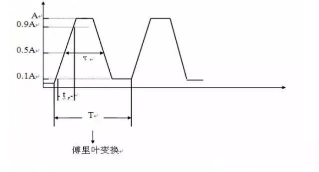
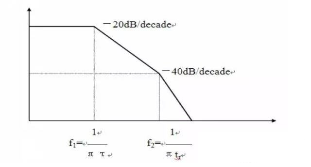
The spectrum of a typical signal:


2. Choosing an AC/DC power filter to suppress conducted and radiated interference on internal and external power lines not only prevents EMI from entering the power grid and harming other circuits, but also protects the equipment itself. It does not attenuate power frequency power. DM (differential mode) interference dominates at frequencies<1 mhz. When cm is>1MHz, it dominates.
3. Ferrite magnetic beads are used to mount on the leads of components for decoupling, filtering, and suppressing parasitic oscillations in high-frequency circuits.
4. Decouple the power supply of the chip as much as possible (1-100nF), and filter (uF) the DC power supply entering the board and the output of the regulator and DC/DC converter.
Pay attention to reducing the inductance of the capacitor lead and increasing the resonant frequency. In high-frequency applications, even four-core capacitors can be used. The selection of capacitance is a very delicate issue, and it is also a means of single board EMC control.
7、 Others
Interference suppression of single boards involves a wide range of aspects, from impedance matching of transmission lines to EMC control of components, from production processes to wiring methods, from coding techniques to software anti-interference. The breeding and birth of a machine is actually an EMC project. The main need is for engineers to inject EMC awareness into their designs.