Basic introduction of EMC test anechoic chamber
 Data:2018-10-29
 Click:2819


Data:2018-10-29
Click:2819
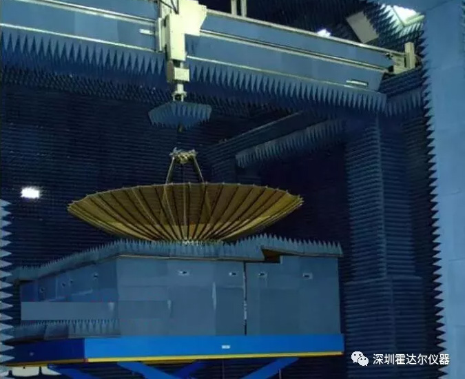
1. anechoic chamber
The anechoic chamber is a closed shielded room that is mainly used to simulate an open field and also used for radiated radio disturbance (EMI) and radiated susceptibility (EMS) measurements. The size of the anechoic chamber and the selection of radio frequency absorbing materials are mainly determined by the outside size and test requirements of the equipment under test (EUT), which can be divided into 1m method, 3m method or 10m method.
2. Composition structure
The main components of the anechoic chamber are shielded chambers and absorbing materials. The shielded room consists of a shielded shell, a shielded door, a ventilation waveguide window and various power filters. According to user requirements, the shielding shell can be welded or assembled. The wave-absorbing material is composed of a single-layer ferrite sheet with a working frequency range of 30MHz~1000MHz and a tapered carbon-containing sponge absorbing material. The tapered carbon-containing sponge absorbing material is made of polyurethane foam in a carbon glue solution It is formed by infiltration and has good flame-retardant properties.
3. Basic classification
Anechoic chamber (anechoic chamber) Usually for radiation test, the test site is divided into three types, namely, full anechoic chamber, semi-anechoic chamber and open field. Radiation tests conducted in these three test sites can generally be considered to conform to the law of electromagnetic wave propagation in free space.
Full wave
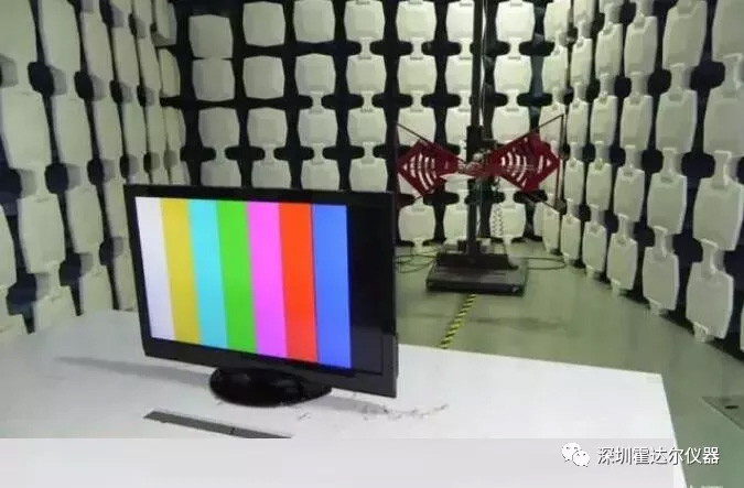
The full electric wave anechoic chamber reduces the interference of external electromagnetic wave signals on the test signal. At the same time, electromagnetic wave absorbing materials can reduce the multipath effect caused by the reflection of walls and ceilings on the test results. It is suitable for emission, sensitivity and immunity experiments. In actual use, if the shielding effectiveness of the shield can reach 80dB~140dB, then the interference to the external environment can be ignored, and the situation of free space can be simulated in a full anechoic chamber. Compared with the other two test sites, the floor, ceiling, and walls of the full-wave anechoic chamber have the least reflection, the least interference from the external environment, and are not affected by the external weather. Its disadvantage is that it is subject to cost constraints and limited testing space.
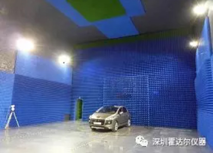
Half wave
The semi-anechoic chamber is similar to the full-anechoic chamber. It is also a six-sided box with shielded design and covered with electromagnetic wave absorbing materials. The difference is that the semi-anechoic chamber uses conductive floors and not covered with absorbing materials. The semi-anechoic chamber simulates an ideal open field situation, that is, the field has an infinite and good conductive ground plane. In the semi-anechoic chamber, since the ground is not covered with absorbing materials, a reflection path will be generated, so that the signal received by the receiving antenna will be the sum of the direct path and the reflected path signal.
Open field
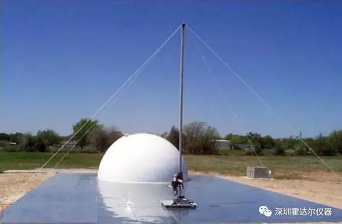
Open area test (OAT) typical open area
Typical open field
It is a flat, open, elliptical or circular test site with uniform conductivity and no reflectors. The ideal open field ground has good conductivity and has an infinite area. The signal received by the antenna is received between 30MHz and 1000MHz. Will be the sum of the direct path and reflected path signals. However, in practical applications, although good ground conductivity can be obtained, the area of the open field is limited, which may cause a phase difference between the transmitting antenna and the receiving antenna. In the launch test, the use of the open field is the same as the semi-anechoic chamber.
4. Performance indicators
Frequency range: 30MHz~18GHz;
(1) Reflection loss of absorbing material: 30MHz~18GHz≥15dB;
(The absorbing material adopts composite absorbing material, that is, the tapered carbon-containing sponge absorbing material is pasted on the ferrite)
(2) Shielding performance of shielded room
Microwave: 1GHz~10GHz≥100dB; 10GHz~18GHz≥90dB;
The test method of the anechoic chamber is generally carried out according to the GB12190-90 standard;
(3) Normalized field attenuation is ±4dB, field uniformity is 0~6dB, in line with GJB2926-97 standard.
5. Main purpose
The anechoic chamber is used to simulate the open field. It is also used for radiated radio disturbance (EMI) and radiated susceptibility (EMS) measurement. The size of the anechoic chamber and the selection of radio frequency absorbing materials are mainly determined by the outside size and test requirements of the equipment under test (EUT), divided into 1m method and 3m method. Method or 10m method.
6. Influencing factors
The factors that affect its performance indicators mainly include: darkroom parameters, antenna measurement errors and other errors.
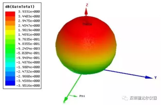
The electrical performance indicators of the microwave anechoic chamber are mainly characterized by the characteristics of the quiet zone. The characteristics of the quiet zone are described in terms of the size of the quiet zone, the maximum reflection level in the quiet zone, cross polarization, field uniformity, path loss, inherent radar cross-section, operating frequency range and other indicators.
The factors that affect the performance of the darkroom are diversified and complex. When using the light emission method and the law of energy physics to simulate the performance of the darkroom, it is necessary to consider the transmission decoupling of the electric wave, the polarization decoupling, and the direction of the standard antenna. Figure factors, the vertical incidence performance and oblique incidence performance of the absorbing material itself, multiple reflections and so on. However, in the actual engineering design process, the performance of the absorbing material is often used as the key determinant of the performance of the darkroom.
1) Cross polarization: Due to the non-strict symmetry of the darkroom structure, the inconsistency of the absorption of various polarized waves by the absorbing material, and the darkroom test system, etc., the electric wave produces the phenomenon of impure polarization during the propagation of the darkroom. If the polarization plane of the antenna to be tested and the transmitting antenna are orthogonal and parallel, and the ratio of the tested field strength is less than -25dB, the cross polarization is considered to meet the requirements.
2) Multipath loss: Uneven path loss will cause the polarization plane of the electromagnetic wave to rotate. If the antenna to be tested rotates in the direction of the wave and the fluctuation of the received signal does not exceed +-0.25 dB, the multipath loss can be ignored.
3) Field uniformity: In the quiet zone of the darkroom, move the antenna to be tested along the axis, and the fluctuations should not exceed +-2dB; on the section of the quiet zone, move the antenna to be tested laterally and up and down, and the received signal fluctuations should not exceed +-0.25 dB.
7. The error of antenna measurement
Error caused by limited test distance
Suppose the antenna to be tested is a planar antenna, and the incoming wave is received along the axis of its main beam. If the test distance is large, the field received by different parts of the antenna to be tested cannot be the same, so there is a square root law phase difference. If the antenna under test is located at the boundary 2D2/λ of the far field area of the source antenna, there is a phase difference of 22.5 degrees between the edge of its aperture and the field of the phase center. If the test distance is doubled, the phase difference is halved.
For antennas with medium sidelobe levels, the distance 2D2/λ is usually sufficient, and the measured gain is about 0.06dB smaller. Shortening the test distance will cause the measurement error to increase rapidly, and the sidelobes will merge with the main beam to form a shoulder. Even into one... Usually the 0.25 dB cone pin reduces the measured gain by about 0.1 dB and causes a slight error in the near side lobes.
reflection
The direct wave is interfered by the reflection from the surrounding objects and forms a field change in the test area. Because the wave path difference changes rapidly as a function of position, the length of the wave is of the order of the wavelength. For example, 20 dB lower than the direct wave The reflected wave can cause a power error of -0.92~+0.83 dB, depending on the difference between the two; the error range of the phase measurement is ±5.7°. However, if the field of the reflected wave is 40dB lower than that of the direct wave, the amplitude and phase of the side exit are only ±0.09 and ±0.6° errors, respectively.
Reflection is particularly harmful in the measurement of low side lobes. A small reflection is coupled to the antenna under test through the main lobe, which can completely cover the direct waves coupled to the side lobes. If the coupled direct and reflected waves have the same intensity, then The measured sidelobe level will increase by about 6 dB, or become a zero point in the measured lobe pattern.
other
The coupling with the near field of reactance may be significant at low frequencies, the alignment error of the measuring antenna, other interference signals, the error caused by the test cable, etc.
Shenzhen Hodall Instruments specializes in the development and production of EMC electromagnetic compatibility test equipment, providing design, development, EMC darkroom, and shielding room; to provide you with a comprehensive EMC (electromagnetic compatibility) solution! Welcome to inquire: 0755-2721 0748