The artificial power network is an important EMC test equipment
 Data:2022-11-30
 Click:3518


Data:2022-11-30
Click:3518
One、 What is artificial power network
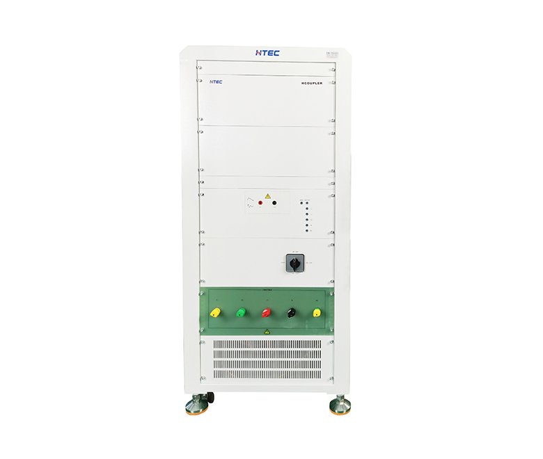
Artificial power supply network, also known as power supply impedance stability network, is an important EMC test equipment, mainly used to measure the continuous interference voltage of switching power supply sent to the power grid along the power line. The artificial power supply network provides stable impedance for the measurement switching power supply in the RF range, and combines the measurement switching power supply with the high-frequency artificial power supply network on the power grid
① Isolator capacitor C3 is used to isolate the power supply voltage, avoid introducing the measurement terminal, and select different capacitors for different influence frequencies. Therefore, the RF interference signal can be connected with the measurement/signal terminal.
② The analog hand is to reproduce the effect of the customer's hand. When it affects the measurement of non-grounded portable electrical equipment, it should be transmitted to the analog hand for testing. Measurement circuit selection The circuit described in CISPRl4 also adopts the measurement method described in CISPRl4.
③ Inductive filter L1 and capacitor C1, C2. Their function is to prevent the RF interference signal from being transmitted from the power supply to the detection equipment, and prevent the electromagnetic interference of the detection equipment from entering the power supply, thus playing an isolation role.
④ The control panel is controlled by the knob switch, and the measurement is controlled by the switch. The "line selection" switch controls "ground wire" and "between lines". During the measurement process, the selection must be made according to the measurement. Another group of switches controls the operating frequency band and attenuator, and selects the operating frequency band button according to different influence frequencies. Press the attenuator button before measuring. When measuring electromagnetic interference, the loss signal is usually not used for measurement. 20 dB attenuators can only be used when the electromagnetic interference is too large to exceed the detection range of influence field strength.
⑤ The 20dB attenuator is composed of a non-type network with a characteristic impedance of 50 Ω. When measuring electromagnetic interference, the attenuator provides a safety protection circuit for the test equipment and equipment to avoid damaging the equipment due to the impact of too large a pulse. Therefore, the attenuator must be pressed before testing. When the electromagnetic interference has enough reading on the influence field intensity meter, the attenuator shall be cut off to make the signal pass directly, so as to eliminate the deviation introduced by the attenuator and improve the measurement accuracy.

Two、 Characteristics of artificial power network
1. The detection phase line can be manually selected or automatically switched through software;
2. Conform to CISPR16-1 specification, and can comply with 16-1 specification, EN, CISPR, FCC, ETS, VCCI, VDE test and other specifications;
3. The operating frequency band is 9kHz - 30MHz, suitable for DC - 63Hz power transmission test;
4. The embedded ammeter can be used to measure the intermittent effect together with the kara detector according to the embedded ammeter, the operation of the CISPR switch and the requirements of 14-1, the influence separation, and then the influence voltage and the receiver connection.
Three、 Classification of artificial power network
There are V type and △ artificial power supply networks; V artificial power network is used to measure different voltages, △ artificial power network is used to measure symmetrical voltages and different voltages.
Symmetrical voltage: RF disturbance voltage between two conductors is generally called differential mode voltage
UnsymmetricalVoltage: wire or terminal or voltage between specific grounding standards
Asymmetrical voltage: RF voltage between electrical midpoint and locating point is also called common mode voltage.
Four、 Artificial power network function
1. It is the way of 50Hz municipal power supply. Because the inductance of the power grid is not large (50) μ H) It is not enough to generate a large impedance at the mains frequency, so the voltage can provide electric energy for the test product, and the side capacitance of the grid (1) μ F) The electromagnetic interference of the power grid can also be further lost.
2. According to the coupling capacitance near the switching power supply (0.1 μ F) The RF disturbance signal generated by the switching power supply enters the receiver.
3. The impedance is stable. Because the impedance of each power grid is different, the disturbance voltage value of switching power supply is also different. Therefore, the standard has a uniform impedance (50) Ω), which is convenient for the comparison of test results.
4. Protect and measure the radio frequency electromagnetic interference generated in the operation of switching power supply (the measurement frequency is 0.15) MHz~30MHz). Using the high impedance of the network inductance under the RF condition can prevent the RF disturbance signal generated by the switching power supply from entering the power grid.

Five, artificial power network regulations
The purpose of applying the artificial power network is to connect the data between the receiver power plug and the power supply, and then have a special high-frequency impedance between the two sides of the receiver power supply, and isolate the power supply, and then use the unbalanced input influence detector to measure the symmetrical influence voltage and different influence voltage. The network shall also include filtering part to consider radio frequency interference in the power supply system. If necessary, auxiliary filter shall also be added. In the detection frequency band, the impedance of the filter should be high enough to avoid causing impedance characteristics of the network. The impedance between the two sides of the power supply AB must be 150 ± 20 Ω, and the phase angle should not exceed ± 20 °.