The generation of a power frequency magnetic field and the purpose of the immunity test
 Data:2022-07-18
 Click:4029


Data:2022-07-18
Click:4029
The power frequency magnetic field is generated by the operating frequency current in the conductor. Low operating frequency magnetic field and long wavelength characteristics. The test waveform is a power frequency sine wave, which can have varying degrees of impact on various electrical and electronic equipment. The power frequency magnetic field anti-interference test can be used to evaluate the performance of household electrical and electronic equipment in power frequency (continuous and short time) magnetic fields, especially for magnetic field anti-interference performance evaluation of magnetic field sensitive equipment such as computer monitors and electricity meters.
The test instrument for the power frequency magnetic field anti-interference test includes an induction coil to generate the magnetic field, and a power frequency excitation power supply to provide the induction coil current.
1. Definitions
The power frequency is the general mains frequency (industrial power frequency), which is 50 Hz in our country, while some countries use 60 Hz.

A power frequency magnetic field is an electromagnetic field induced by a power frequency electric field, which is mainly generated by the power frequency current in the topic, or a small amount is generated by other nearby devices (such as the leakage magnetic flux of a transformer).
1.1 PFMF Disturbance Characteristics
V=f λ Where V is the wave velocity and f is the frequency, λ Is the wavelength.

Power frequency magnetic fields are characterized by low frequency (50) Hz), V which is a constant value with a longer natural wavelength. Under normal circumstances, the magnetic field generated by power frequency current is relatively stable and has a small magnetic field strength. However, in a fault or emergency situation, the magnetic field generated by the current is unstable and the magnetic field migration is relatively large. However, the duration is relatively short. This is also one of the bases for the following classification of test levels.
1.2 Purpose
The purpose of this inspection is to check the performance of electronic and electrical equipment under the influence of such magnetic field interference, i.e., the degree of immunity of the system and equipment to power frequency magnetic fields.
2. Test level
The preferred range of magnetic field test levels for stable, continuous, and short-term effects is as follows:
Stable continuous magnetic field test level:

The magnetic induction intensity is expressed in A/m, and 1 A/m corresponds to a magnetic induction intensity of 1.26 in free space μ T。
Short time test level for 1s-3s:

The PFMF test level is typically selected based on actual installation and environmental conditions:
Level 1: Sensitive devices with electron beams, represented by monitors and electron microscopes.
Level 2: Good environmental protection represented by industrial areas, hospitals, and offices.
Level 3: Business districts, control buildings, and machine rooms of high-voltage substations represented by environmental protection
Level 4: Typical industrial environment represented by heavy industrial plants, mines, and high-voltage substation control rooms
Level 5: Heavy industrial plant and mine switching stations represented by power plants and harsh industrial environments
3. Test Layout
The basic configuration of the PFMF test includes a ground reference plane (GRP), a device under test (EUT), an induction coil, and a power frequency magnetic field generator.
Almost all electromagnetic compatibility tests are used for GRP. All requirements are as follows: If the material is 0.25mm and other metal plates are used, the minimum thickness of the above copper or aluminum plates is 0.65mm, and the minimum size of the GRP is 1m * 1m. However, if the length or width of the EUT is greater than this value, it should be adjusted to at least the corresponding value, that is, the final size of the GRP depends on the EUT, and the size of the GRP is securely connected to the laboratory;
The EUT should be placed on a GRP with a 0.1m thick insulation support between them. The EUT housing is connected through its own ground terminal and ground terminal GRP. All cables (if satisfied) should be 1m long and exposed to the magnetic field. If a filter is used, it should be connected to a cable at a distance of EUT1m, and the filter should be connected to the GRP.
The induction coil should be placed at least 1 meter away from the laboratory walls and other magnetic objects. When conducting horizontal polarization field tests on the induction coil, a portion of the GRP coil can be used as the bottom edge of the coil.
The test current generator should be placed at a distance of no more than 3 meters from the coil, and one end of it should be connected to the GRP.
During the testing process, the coil should be able to surround the test equipment, and its size should be such that the minimum distance between the coil and the test equipment shell is equal to 1/3 of the size of the test equipment considered. For large equipment, which is relatively large, the induction coil can be made of conductors through a "C" shaped cross-section or a "T" shaped cross-section for sufficient mechanical stability. The test volume is determined by multiplying the test area of the coil (60% x 60% of each side) by the height (50% corresponds to the shorter coil).
4. Contents of the test plan
Ensure that the electromagnetic conditions (laboratory background electromagnetic field should be at least 20 dB lower than the selected test level, otherwise, the test should be conducted in a Faraday cage) and climatic conditions (temperature 15-35) ℃, relative humidity 25% - 75%, atmospheric pressure 86-106kPa) meet the requirements.
Determine the type of test magnetic field (stable duration or short duration), and determine the test level.
Correct operation of EUT pre verification:
Test: Taking a desktop device as an example, the immersion method EUT should be used for the test. The EUT should be placed and connected according to the actual use requirements, and placed in the center of the magnetic field coil to test the anti-interference performance of the EUT exposed to magnetic fields in different polarization directions. The coil should be rotated 90 times three degrees, and then the same test should be performed, that is, the duration in each direction of X, Y, and Z is generally 300 seconds, and the time can be adjusted according to the actual situation. For some large equipment or systems, it is not necessary to place them all in the magnetic field, but only to place the sensitive devices in the system in the center of the magnetic field for separate testing.
5. Evaluate test results
The test results shall be classified based on the functional loss or performance degradation of the equipment under test. The relevant performance level is determined by the equipment manufacturer or experimental demander, and GB17626 recommends classification according to the following requirements:
Normal performance within the limits specified by the manufacturer, client, or buyer;
Temporary loss or degradation of function or performance, but it can recover automatically after the disturbance stops without operator intervention;
Temporarily losing or reducing function or performance, but requiring operator intervention to recover;
Unrecoverable loss of functionality or performance degradation due to device hardware or software damage or data loss.
Generally speaking, item a is qualified, item c and item d are unqualified, and item b needs to be determined through consultation with the customer based on the usage of the equipment.
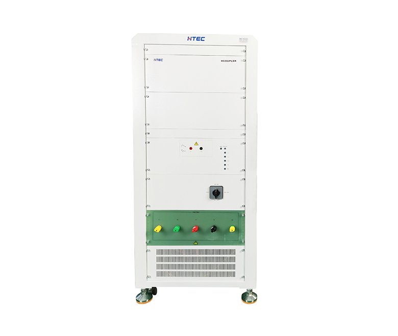
6. Test equipment
The PFMF test instrument includes an induction coil for generating magnetic fields, a working frequency excitation power supply for providing induction coil current, and a working frequency excitation power supply GRP (refer to the grounded version) for providing induction coil current, as well as auxiliary equipment such as magnetic field probes, electronic energy meters, and so on.
The technical parameter requirements are as follows:
Output current range during stable and continuous operation: 1A-100A, divided by the coil factor;
Output current range: 300A-1000A, divided by coil factor;
The total output current distortion rate is less than 8%;
Sinusoidal waveform output current waveform;
Short working time: 1-3s;
Induction coils come in three forms:
(1) A square induction coil with a standard side length of 1m and a field strength tolerance of within ± 3.0dB can accommodate EUT sizes of 0.6m * 0.6m * 0.5m (l * w * h);
(2) A square double induction coil, also known as a Helmholtz coil, has a standard side length of 1m, a distance of 0.8m between the two coils, and a field strength uniformity of better than ± 0.2dB;
(3) For large cabinet type equipment, the coil is customized according to the EUT. In order to ensure uniformity, each side of the coil reaches the EUT in both horizontal and vertical directions, and the minimum distance from the shell is 0.2m and 0.3m.
7. Examples
Taking a Class III medical device as an example, based on actual installation and environmental conditions, it can be determined that the power frequency magnetic field test level is Level 2, that is, using Level 3 A/m magnetic field strength. This is based on the current YY050 judgment that the magnetic field strength of 0505-2012IEC300601 has already specified the use of 3001A/m test, and the domestic has not yet been converted in a timely manner. The test arrangement is as follows: